Class Reference drawingField
The head class of the drawing. More...
Member
Detailed Description
Each layout window has exactly one drawingField, reached as layout->drawing. That object is the design itself: cells, the current cell, load and save, and the helpers that place points and then call box(), path() or polygon(). Coordinates in the file are integers; databaseunits converts them to metres, userunits is what dialogs show. firstCell is the linked list of all cells; currentCell is the cell you see and edit. New shapes go on activeLayer unless you pass another layer. The same members can be typed in the command-line toolbar without commas; in a macro you need normal C++ punctuation.
Example:
// set active layer
layout->drawing->activeLayer=9;
// create a box
layout->drawing->point(220000,-140000);
layout->drawing->point(380000,-260000);
layout->drawing->box();
//create a polygon
layout->drawing->point(380000,-260000);
layout->drawing->point(570000,-260000);
layout->drawing->point(570000,-180000);
layout->drawing->point(470000,-180000);
layout->drawing->point(470000,-210000);
layout->drawing->point(380000,-210000);
layout->drawing->polygon();
// change active layer
layout->drawing->activeLayer=6;
// create a path
layout->drawing->point(380000,-140000);
layout->drawing->point(470000,-140000);
layout->drawing->point(470000,-180000);
layout->drawing->path();
Member Function Documentation
int drawingField::activeLayer
This is the default layer. Otherwise specified all new shapes will be added to this layer. Also it will be the default layer for all popup dialogs.
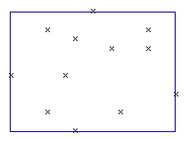
void drawingField::addBoundingBox()
A bounding box of the prior entered points is add to the active layer.
cellList* drawingField::addCell()
Adds a cell to the drawing. A pointer to the new cellList is returned. The new cell is unnamed.
cell *c=layout->drawing->addCell()->thisCell;
c->cellName="my new cell";
Returns: a pointer to the new cellList entry.
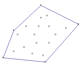
void drawingField::addConvexPolygon()
A convex polygon around all prior entered point is added to the active layer.
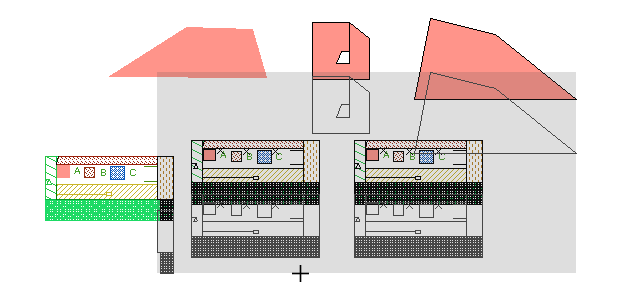
void drawingField::addHierarchy(int nx,int ny)
Adds a additional hierarchy level in the current displayed cell by moving its elements into new created subcells. nx times ny subcells will be created and all elements over its checkerboard with maximal the checkerboard size will be moved into the subcell. The resulting design is not changes. (introduced with release 20220129)
void drawingField::alignBottom()
The bottom edge of the selected elements is aligned to the before entered point.
void drawingField::alignCenterXY()
Selected elements will be centered in X and Y direction to the center of a rectange created by two previous entered points.
void drawingField::alignCenterX()
Selected elements will be centered in X direction to the center of a rectange created by two previous entered points.
void drawingField::alignCenterY()
Selected elements will be centered in Y direction to the center of a rectange created by two previous entered points.
void drawingField::alignLeft()
The left edge of the selected elements is aligned to the before entered point.
void drawingField::alignRight()
The right edge of the selected elements is aligned to the before entered point.
void drawingField::alignTop()
The top edge of the selected elements is aligned to the before entered point.
void drawingField::alignValue(int distance)
Selected elements are moved so that the distance of the before entered points is set to distance
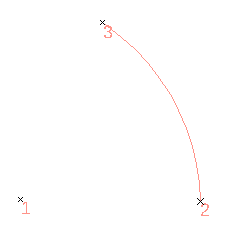
void drawingField::arc()
Add a arc path to the current cell. Three coordinates had to be entered before with the point command.
void drawingField::arrayCopy(int nx, int ny)
If one coordinate was added before with the point() or p() command, selected elements are copyed in an array with steps of p1.x() and p1.y() releated to the selected shapes. If two coordinate were added before with the point() or p() command, selected elements are copyed and moved by (p2-p1).x() and (p2-p1).y() per step.
void drawingField::autoRuler(point pos)
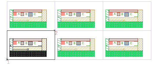
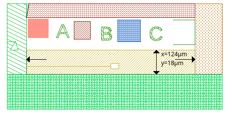
Performs an automatic measurement at pos and places a permanent ruler.
void drawingField::bezier2()
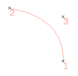
Add a second order bezier path to the current cell. Three coordinates had to be entered before with the point command.
void drawingField::bezier3()
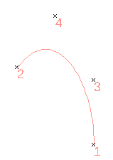
Add a third order bezier path to the current cell. Four coordinates had to be entered before with the point command.
void drawingField::box()
Add a box to the current cell. Two coordinates had to be entered before with the point command.
void drawingField::boxDeselect()
All boxes in the current cell are deselected.
void drawingField::boxSelect()
All visible boxes in the current cell are selected.
void drawingField::BSpline()
a B-Spline is createed from the prior entered points
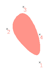
void drawingField::cDeselect()
If one coordinate was added before with the point or p command, the nearest cellref is deselected. If two coordinate were added before with the point or p command, all cellrefs in the region p1,p2 are deselected.
void drawingField::cSelect()
If one coordinate was added before with the point or p command, the nearest cellref is selected. If two coordinate were added before with the point or p command, all cellrefs in the region p1,p2 are selected.
void drawingField::cellRef(string s)
Add a cellref to the current cell. One coordinate had to be entered before with the point command. This point is the reference point of the insert cellref.
There is no check for circular references. e.g. if you add a reference from cellA to cellB, but cellB has a cell reference to cellA, you may get trouble and the display of the design may fail.
void drawingField::cellrefarray(string s,int x, int y)
Adds an array of cell references to the current cell. Enter two points with point() first: the first is the origin of the lower-left instance, the second is the origin of the neighbour one column right and one row up (same two points as in the GUI). The array has x instances in X and y in Y. There is no check for circular references (see drawingField::cellRef).
| Parameter: | |
|---|---|
| s | name of the cell to refer |
| x | number of instances along X |
| y | number of instances along Y |
void drawingField::cellUp()
A cell which uses the current cell is set as the current cell.
void drawingField::centerX()
Selected element are aligned to the entered point in the x axis.
void drawingField::centerXY()
Selected element are aligned to the entered point.
void drawingField::centerY()
Selected element are aligned to the entered point in the y axis.
void drawingField::circle()
Add a circular polygon to the current cell. Two coordinates had to be entered before with the point command. The first entered point is the center, the second point mark the radius.
void drawingField::circleBox()
Add a circular polygon to the current cell. Two coordinates had to be entered before with the point command. The two points mark a bounding square in which the circle is added.
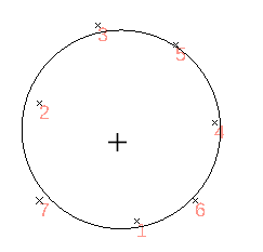
void drawingField::circleFit()
Add a circular polygon to the current cell. The circle is fitted to the before entered points.
void drawingField::clearMirrorx()
In selected text elements and cell references the mirror flag is cleared.(introduced with release 20220808)
void drawingField::clearPoints()
Delete all entered point.
void drawingField::clearProperties()
All element properties in this design are removed. (introduced with release 20230828)
void drawingField::closeToPolygon()
Closes selected path elements to a polygon.
void drawingField::closedPathToPolygon()
Converts selected path elements to a polygon, if the last point is identical with the first point.
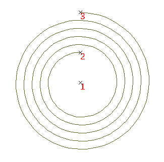
void drawingField::coil(int turns)
Add a coil to the current cell. Three coordinates had to be entered before with the point command.
void drawingField::compareCell(string s)
Compares the current cell with the cell s. Non identical elements will be selected in both cells. All other elements will be deselected.
void drawingField::compareCellXor(string cell)
Compares the current cell with cell. An XOR of each use layer will be made. The result will be added to a new cell.
void drawingField::copy()
If one coordinate was added before with the point() or p() command, selected elements are copyed and moved by p1. If two coordinate were added before with the point() or p() command, selected elements are copyed and moved by p2-p1.
void drawingField::copyArea(rect r, int layerSource, int layerDest)
Copies every shape on layerSource that touches or overlaps rectangle r onto layerDest. Hierarchy is ignored: shapes inside referred cells are copied as well.
| Parameter: | |
|---|---|
| r | rectangle in database units |
| layerSource | source layer number |
| layerDest | destination layer number |
void drawingField::copyArea(double minArea, double maxArea, int layerDest, int layerSource)
Copies every shape on layerSource whose area is between minArea and maxArea onto layerDest. Hierarchy is ignored: shapes inside referred cells are copied as well.
| Parameter: | |
|---|---|
| minArea | smallest area to copy |
| maxArea | largest area to copy |
| layerDest | destination layer number |
| layerSource | source layer number |
void drawingField::copyCurrentCell()
The current cell is copied. The copied cell is name oldcellname_copy.
void drawingField::copyDimension(int minWidth, int maxWidth, int minLength, int maxLangth, int layerDest, int layerSource=-1)
Copies shapes whose short side is between minWidth and maxWidth and whose long side is between minLength and maxLangth onto layerDest. Hierarchy is ignored. If layerSource is not -1, only that layer is scanned.
| Parameter: | |
|---|---|
| minWidth | smallest short-side width |
| maxWidth | largest short-side width |
| minLength | smallest long-side length |
| maxLangth | largest long-side length |
| layerDest | destination layer number |
| layerSource | source layer, or -1 for all layers |
void drawingField::copyLayer(int sourcelayer, int sourcedatatype, int destLayer)
Copies all shapes on sourcelayer with sourcedatatype in the whole design onto destLayer. If sourcedatatype is -1, every datatype on sourcelayer is copied.
| Parameter: | |
|---|---|
| sourcelayer | source layer number |
| sourcedatatype | GDS datatype, or -1 for all |
| destLayer | destination layer number |
void drawingField::copyLayerSized(int sourcelayer, int destinationlayer, int size,int type)
Makes a flattened copy of sourcelayer onto destinationlayer and sizes the copy. type uses the same modes as cell::sizeAdjustSelect.
| Parameter: | |
|---|---|
| sourcelayer | source layer number |
| destinationlayer | destination layer number |
| size | size amount in database units |
| type | sizing mode as in sizeAdjustSelect |
void drawingField::copyLayerSizedAsym(int sourcelayer, int destinationlayer, int sizeX, int sizeY)
Makes a flattened copy of sourcelayer onto destinationlayer with different X and Y sizing.
| Parameter: | |
|---|---|
| sourcelayer | source layer number |
| destinationlayer | destination layer number |
| sizeX | size amount in X |
| sizeY | size amount in Y |
cell * drawingField::copyLayerToCell(int layer)
All shapes in the currentCell on layer will be copied to a new cell with the name currentCellName-layerName. Cellreferences will be handeled in the same way. A pointer to the new cell is returned. If the current Cell does not contain shapes on layer NULL is returned.
Returns: a pointer, or NULL if none.
void drawingField::copyMirror()
Selected elements are copied. The copies shapes are mirrored between p1 and p2. Two coordinates had to be added before with the point() or p() command.
void drawingField::copyOverlapping(int layerA,int layerB, int layerOutA, int layerOutB=-1)
Copies shapes on layerA that overlap shapes on layerB. Results go to layerOutA and layerOutB. A negative output layer skips that side. Hierarchy is ignored.
| Parameter: | |
|---|---|
| layerA | first input layer |
| layerB | second input layer |
| layerOutA | destination for matching layerA shapes |
| layerOutB | destination for matching layerB shapes, or -1 to skip |
void drawingField::copyTouching(int layerA,int layerB, int layerOutA, int layerOutB=-1)
Copies shapes on layerA that touch shapes on layerB. Results go to layerOutA and layerOutB. A negative output layer skips that side. Hierarchy is ignored.
| Parameter: | |
|---|---|
| layerA | first input layer |
| layerB | second input layer |
| layerOutA | destination for matching layerA shapes |
| layerOutB | destination for matching layerB shapes, or -1 to skip |
void drawingField::copyTouchingOrOverlapping(int layerA,int layerB, int layerOutA, int layerOutB=-1)
Copies shapes on layerA that touch or overlap shapes on layerB. Results go to layerOutA and layerOutB. A negative output layer skips that side. Hierarchy is ignored.
| Parameter: | |
|---|---|
| layerA | first input layer |
| layerB | second input layer |
| layerOutA | destination for matching layerA shapes |
| layerOutB | destination for matching layerB shapes, or -1 to skip |
void drawingField::crossSection()
Create a cross section view in a new cell between two prior entered points.
void drawingField::crossSection(point p1, point p2)
Create a cross section view in a new cell between the point p1-p2.
| Parameter: | |
|---|---|
| p1 | p1 |
| p2 | p2 |
cell* drawingField::currentCell
This is a pointer on the cell displayed.
void drawingField::cut()
Selected elements between p1 and p2 are separated. Two coordinates had to be added before with the point() or p() command.
double drawingField::databaseunits
All coordinates are integer. This value is the factor of these integers to the real value.
double drawingField::DBUToUu(int databaseunits)
converts a value in databaseunits to userunits (introduced with release 20260430)
Returns: a double.
void drawingField::delPoint()
Delete the last entered point.
void drawingField::deleteAllCell()
All cells of the current design will be deleted.
void drawingField::deleteCell(cell * cellPtr)
cellPtr will be deleted. All cell references to this cell will be removed as well.
void drawingField::deleteCurrentCell()
The current cell is deleted.
void drawingField::deleteExceptOneLayer(int layer)
All element not on the layer "layer" will be delete in any cell of the current drawing. Text elements will even be deleted on this layers as it is ignored often in mask production. So the function is useful for preparing data for mask production. Use extractLayer instead to keep text elements.
void drawingField::deleteLayer(int layer)
All shapes on the layer layer will be removed on in all cells of the design.
void drawingField::deleteLayer(int layer, int datatype)
All shapes on the layer layer having datatype will be removed on in all cells of the design.
void drawingField::deleteLayers(intList layers)
Shapes on every layer listed in layers are deleted in every cell of the current drawing. The datatype is ignored. (introduced with release 20261014)
void drawingField::deleteSelect()
Selected elements/points in the currentCell are deleted.
void drawingField::deleteText()
All text elements will be deleted in all cells of the design.
void drawingField::deleteZeroWidthPath()
All path elements with a width of zero or less will be deleted in all cells of the design.
void drawingField::derivedLayer(int layerA, int layerB, int resultLayer, string operation)
Builds a derived layer on resultLayer from layerA and layerB. The operation string chooses the rule (same names as in the GUI derived-layer list).
| Parameter: | |
|---|---|
| layerA | first input layer |
| layerB | second input layer |
| resultLayer | layer that receives the result |
| operation | one of the operation names below |
These derived operations are available:
| Operation: | Result: |
|---|---|
| avoiding | The shapes on layerA that are completely outside and do not touch the shapes on layerB |
| butting | The shapes on layerA that abut the shapes on layerB; the shapes on layerA must have at least one coincident edge with the shapes on layerB and must otherwise be completely or partially outside the shapes on layerB |
| buttingOrCoincident | The shapes on layerA that have any coincident edges with the shapes on layerB; Shapes may abut, overlap, or be completely contained |
| buttingOrOverlapping | The shapes on layerA that touch, overlap, or are contained within the shapes on layerB; like “touching” except this may have parameters |
| buttOnly | The shapes on layerA that abut – but do not overlap – any shapes on layerB (i.e., have only a coincident edge in common) |
| coincident | The shapes on layerA that have any coincident edges with the shapes on layerB; Some part or all of the shape on layerA must overlap the corresponding shape on layerB; Shapes that abut only are excluded |
| coincidentOnly | The shapes on layerA that are completely contained within, and have at least one coincident edge with, the shapes on layerB |
| enclosing | The shapes on layerA that completely contain one or more shapes on layerB |
| inside | The shapes on layerA that are completely contained within the shapes on layerB (coincident edges are allowed) |
| outside | The shapes on layerA that are completely outside of the shapes on layerB; Shape edges may abut but not overlap |
| overlapping | The shapes on layerA that are completely or partially contained within the shapes on layerB; Shapes that abut but do not overlap are excluded |
| straddling | The shapes on layerA that overlap at least one edge of the shapes on layerB. At least one point of the layerA shape must be outside the corresponding shape on layerB. Shapes that abut but do not overlap are excluded. |
| touching | The shapes on layerA that abut, overlap or are contained within the shapes on layerB |
void drawingField::deselectActiveLayer()
All elements on the active layer are deselected.
void drawingField::deselectAll()
All elements in the current cell are deselected.
void drawingField::densityFill(int layer, double density, int shapeSpace, int minWidth, int minSpace, int frameSize, int grid=0)
Fills layer with dummy shapes until the coverage reaches density (percent). Added shapes keep minWidth and minSpace, stay at least shapeSpace away from existing geometry, and respect frameSize. Optional grid (database units, default 0) snaps vertices; 0 turns the grid off.
| Parameter: | |
|---|---|
| layer | layer to fill |
| density | target coverage in percent |
| shapeSpace | minimum distance to existing shapes |
| minWidth | minimum width of added shapes |
| minSpace | minimum space between added shapes |
| frameSize | frame around the fill region |
| grid | snap pitch, or 0 for none |
void drawingField::dot()
Add a box to the current cell. Two coordinates had to be entered before with the point command.The first point is the center point, the second point is a corner point.
void drawingField::ellipse()
Add a ellipse to the current cell. Two coordinates had to be entered before with the point command. The two points mark a bounding square in which the ellipse is added.
bool drawingField::existCellname(string s)
Returns: true if a cell with the name s exist.
void drawingField::extractLayer(int layer)
All elements not on the layer "layer" will be delete in any cell of the current drawing.
void drawingField::extractLayers(intList layers)
All elements whose layer is not listed in layers are deleted in every cell of the current drawing. Elements on a listed layer stay. (introduced with release 20261013)
void drawingField::extractCurrentCell()
The current is flatten multilevel and all other cell are removed
void drawingField::fAllDeselect()
If two coordinate were added before with the point or p command, all element in the region p1,p2 are deselected. All Points of the element must be inside the region.
void drawingField::fAllSelect()
If two coordinate were added before with the point or p command, all element in the region p1,p2 are selected. All Points of the element must be inside the region.
void drawingField::fDeselect()
If one coordinate was added before with the point or p command, the nearest element is deselected. If two coordinate were added before with the point or p command, all element in the region p1,p2 are deselected.
void drawingField::fSelect()
If one coordinate was added before with the point or p command, the nearest element is selected. If two coordinate were added before with the point or p command, all element in the region p1,p2 are selected.
string drawingField::fileType
Gives information on the type of the file, if it was loaded.
void drawingField::fillSelectedShapes(cell * cellref, int align=0)
Selected shapes are filled with references to the given cellref. The references are placed in a array and only placed, if the bounding box is complete inside one selected shape.
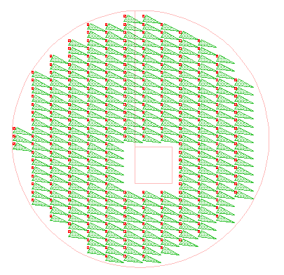
The optional parameter align defines the aligment with: (introduced with release 20211122)
| Algin: | Result: |
|---|---|
| 0 | align the the origin of the coordinate system |
| 1 | align to the lower left corner of the bounding box of each shape |
| 2 | align to the lower right corner of the bounding box of each shape |
| 3 | align to the upper left corner of the bounding box of each shape |
| 4 | align to the upper right corner of the bounding box of each shape |
| Parameter: | |
|---|---|
| cellref | pointer; NULL is invalid |
| align | align |
void drawingField::fillSelectedShapes(string cellname, int align=0)
Identical as the method above, but the cellreference is given by name instead of a pointer. The optional parameter align defines the aligment (introduced with release 20211122)
| Parameter: | |
|---|---|
| cellname | name |
| align | align |
cell* drawingField::findCell(string s)
Returns: pointer to the cell with name s. Null if the name does not exist.
stringList drawingField::findCellRegExp(string regExp)
Returns: a list of existing cells with a cellname matching regExp.
cell* drawingField::findTopCell()
Returns: cell which is not referred by an other cell.
cellList* drawingField::firstCell
This is a list of all cells in the drawing.
void drawingField::flat()
Selected cellrefs and cellrefarrays are flatten.
void drawingField::flatAll()
Selected cellrefs and cellrefarrays are flatten. If the the cellrefs contain more cellrefs, they are flatten as well.
pointArray drawingField::getPoints()
Returns: a pointArray of all previous entered points with the point, pointRel, p, pRel and mouse entered points.
void drawingField::getView(double *scale,int *x,int *y)
Writes the current view into the three pointers: scale and the drawing position at the screen centre x, y.
| Parameter: | |
|---|---|
| scale | pointer receiving the display scale |
| x | pointer receiving the centre X in drawing units |
| y | pointer receiving the centre Y in drawing units |
string drawingField::getViewMacro()
a small macro is generated that will restore the current view of the display.
#!/usr/bin/layout
#name=View Macros
#help=View Set Macro automatic generated

int main(){
layout->drawing->setCell("test");
layout->drawing->setView(0.096321526,1087,7893);
}
Returns: a string.
int drawingField::gridMinimum
If an automatic grid is used, the grid will never less this value.
int drawingField::gridOffsetX
This member holds the actual grid-offset in X in drawingunits
int drawingField::gridOffsetY
This member holds the actual grid-offset in Y in drawingunits
int drawingField::gridX
This member holds the actual X-grid in drawingunits
int drawingField::gridY
This member holds the actual Y-grid in drawingunits
bool drawingField::gridauto
If this member is true, the grid is automaticly change after changing the scale.
void drawingField::group()
All selected elements are moved to a new cell. A correlating cellref will be added. If a identical cell exists, a cellref to this cell is added and the selected elements are deleted.
int drawingField::groupGlobal()
All selected elements are moved to a new cell. A correlating cellref will be added. If a identical cell exists, a cellref to this cell is added and the selected elements are deleted. Identical structures in complete library are also replaced by a cellref. The number of replaced structures is returned.
Returns: an integer.
void drawingField::groupSimple()
All selected elements are moved to a new cell. A correlating cellref will be added.
int drawingField::groupStructure()
All selected elements are moved to a new cell. A correlating cellref will be added. If a identical cell exists, a cellref to this cell is added and the selected elements are deleted. Identical structures in the current cell are also replaced by a cellref. The number of replaced structures is returned.
Returns: an integer.
void drawingField::importFile(string filename)
The filename is added to the current design. So the list of all cell in the design is extended by the cells in filename. Aleady existing cells with identical name and identical contants are not imported.
void drawingField::importViaFile(string filename)
Similar to importFile but it imports the via data from tlef file only. (introduced with release 20201215)
void drawingField::importView(string library,string cellName,string viewName)
Adds the OpenAccess view library / cellName / viewName to the current design.
| Parameter: | |
|---|---|
| library | OpenAccess library name |
| cellName | cell name |
| viewName | view name |
void drawingField::invertSelect()
The selection in the current cell is inverted.
string drawingField::libname
Name of this libary as used in GDS-file or OASIS-file.
void drawingField::mapLayer(layertranslator *t)
all elements are maped with layerTranslator t.
void drawingField::mergeSelect()
Selected elements in the currentCell are merged. The orginal shape is use to build the path to inner polygons. The function works for a small amount of elements. Use the booleanHandler to merge a large amount of element.
void drawingField::mirror()
Selected elements are mirror between p1 and p2. Two coordinates had to be added before with the point() or p() command.
int drawingField:: mmToDBU(double millimeter)
converts a value in millimeter to databaseunits (introduced with release 20260430)
Returns: an integer.
bool drawingField::modified()
Returns: true ,if the design was modifies after the last save
void drawingField::move()
If one coordinate was added before with the point() or p() command, selected elements are moved by p1. If two coordinate were added before with the point() or p() command, selected elements are moved by p2-p1.
void drawingField::moveLayer(int sourceLayer, int sourcedatatype, int destLayer)
Moves all shapes on sourceLayer with sourcedatatype in the whole design onto destLayer. If sourcedatatype is -1, every datatype on sourceLayer is moved.
| Parameter: | |
|---|---|
| sourceLayer | source layer number |
| sourcedatatype | GDS datatype, or -1 for all |
| destLayer | destination layer number |
void drawingField::moveOrigin()
The orgin of the current cell is move to the prior entered point. All references to this cell are adjusted.
void drawingField::moveX()
Selected elements are moved in x axis by p2-p1. Two coordinates had to be added before with the point() or p() command.
void drawingField::moveY()
Selected elements are moved in y axis by p2-p1. Two coordinates had to be added before with the point() or p() command.
int drawingField::mToDBU(double meter)
converts a value in meter to databaseunits (introduced with release 20260430)
Returns: an integer.
void drawingField::newCell()
A new empty cell will be added, named with an unused cell name and it is set as current cell.
cell * drawingField::oaFindCell(string libName,string cellName,string viewName,stringList parameterName=stringList(),stringList parameterValue=stringList() )
Finds the OpenAccess cell libName / cellName / viewName and loads it if needed. parameterName and parameterValue instantiate a parametric cell. Not available in Python and Ruby.
| Parameter: | |
|---|---|
| libName | OpenAccess library |
| cellName | cell name |
| viewName | view name |
| parameterName | PCell parameter names |
| parameterValue | matching PCell parameter values |
Returns: a pointer to the cell, or NULL if it does not exist or OpenAccess is not available.
string drawingField::oaGetCellName(string libName,string cellName,string viewName,stringList parameterName=stringList(),stringList parameterValue=stringList() )
Loads the OpenAccess cell if needed and returns its LayoutEditor cell name. parameterName and parameterValue instantiate a parametric cell. Not available in Python and Ruby.
| Parameter: | |
|---|---|
| libName | OpenAccess library |
| cellName | cell name |
| viewName | view name |
| parameterName | PCell parameter names |
| parameterValue | matching PCell parameter values |
Returns: the cell name, or an empty string if the cell does not exist or OpenAccess is not available.
void drawingField::openFile(string filename)
A file with the name filename is opened. The previous design will be closed.
void drawingField::openView(string library,string cellName,string viewName)
Opens the OpenAccess view library / cellName / viewName as the current layout.
| Parameter: | |
|---|---|
| library | OpenAccess library name |
| cellName | cell name |
| viewName | view name |
void drawingField::p(double x,double y)
Set the Command Mode and add the point p(x,y) in user units.
void drawingField::pDeselect()
If one coordinate was added before with the point or p command, the nearest point is deselected. If two coordinate were added before with the point or p command, all points in the region p1,p2 are deselected.
void drawingField::pDir(double length,double dir)
Set the Command Mode and add the point p(length,dir) in user units relative to the last point entered. Dir is the angle to the x-axis.
void drawingField::pMove(double x,double y)
The last entered point is moved by point p(x,y) in user units.
void drawingField::pRel(double x,double y)
Set the Command Mode and add the point p(x,y) in user units relative to the last point entered. The first entered point is set absolute.
void drawingField::pSelect()
If one coordinate was added before with the point or p command, the nearest point is selected. If two coordinate were added before with the point or p command, all points in the region p1,p2 are selected.
void drawingField::path()
Add a path to the current cell. Two coordinates had to be entered before with the point command.
void drawingField::pathDeselect()
All path elements in the current cell are deselected.
void drawingField::pathSelect()
All visible path elements in the current cell are selected.
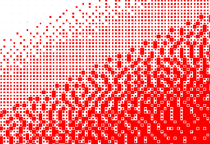
void drawingField::pixelMap(int pixelX ,int pixelY,string functionName)
Builds a greyscale pixel array from a C++ function named functionName. That function must return a double between 0 and 1 for each pixel coordinate. pixelX and pixelY are the array size. Pixel-import settings from setup apply. Python and Ruby are not supported. (introduced with release 20210625)
| Parameter: | |
|---|---|
| pixelX | number of pixels in X |
| pixelY | number of pixels in Y |
| functionName | name of a C++ function returning 0…1 |
Example:
#!/usr/bin/layout
#name=pixelMap example
#help=Example macro for the pixelMap function

double greyFunc(int x, int y)
{
        return 0.5*(1+math::sin(x*y*1e-6));
}

int main()
{
 setup::pixelResolution=250000; //Dots per meter
 setup::pixelMethod=1;
 setup::pixelDither=1; //Floyd-Steinberg=0, Jarvis=1, Sierra=2
 setup::pixelInvert=false; //true = shapes for black, false = shapes for white
 setup::pixelMinSize=0.375; //Minimum shape size relative to the pixel size
 setup::pixelSteps=2;

 int xPixels = 500;
 int yPixels = 250;

 layout->drawing->pixelMap(xPixels,yPixels,"greyFunc");
 layout->drawing->scaleFull();
 return 0;
}
Resulting Design:
void drawingField::pointMove(int x,int y)
The last entered point is moved by point p(x,y).
void drawingField::pointMove(point p)
The last entered point is moved by point p(x,y).
void drawingField::point(point p)
Set the Command Mode and add the point p.
void drawingField::point(int x,int y)
Set the Command Mode and add the point p(x,y) in drawing units.
void drawingField::pointRel(int x,int y)
Set the Command Mode and add the point p(x,y) in drawing units relative to the last point entered. The first entered point is set absolute.
void drawingField::pointRel(point p)
Set the Command Mode and add the point p relative to the last point entered. The first entered point is set absolute.
void drawingField::polygon()
Add a polygon to the current cell. Three coordinates had to be entered before with the point command.
void drawingField::polygonArc()
Add a arc polygon to the current cell. Three coordinates had to be entered before with the point command.
void drawingField::polygonDeselect()
All polygons in the current cell are deselected.
void drawingField::polygonSelect()
All visible polygons in the current cell are selected.
void drawingField::prepareUndo()
Save the cell for the next undo.
string drawingField::previousCell
The name of the cell used before the current cell.
void drawingField::redo()
Revoke the last undo.
void drawingField::relink(const string cellName)
Selected cell references in the current cell are relinked to a cell with the name cellName. There are no checks for circular references. A circular reference may cause a programm crash.
| Parameter: | |
|---|---|
| cellName | Selected cell references in the current cell are relinked to a cell with this name. |
void drawingField::removeCellArrays()
All cell array references in the design are flatten to cell references.
void drawingField::removeNotOrthogonalCellref()
remove not ortogonal cellrefs
void drawingField::removeOverlap()
removes overlap of shape on the active layer
void drawingField::removeOverlap(int layer)
removes overlap of shape on layer
void drawingField::removeRotatedCellArrays()
Cell array with a rotation to the referred cell are removed by added a further hierarchy level with a rotated reference to a cell with an unrotated array.
void drawingField::removeScaledCellref()
remove scaled cellrefs
void drawingField::resetUndo()
Reset the last undo.
void drawingField::rotate(double angle)
Selected elements are rotate by angle at a point prior added with the point() or p() command.
Parameter: angle rotating angle in deg. Selected elements are rotate by angle at a point prior added with the point() or p() command.
void drawingField::saveFile(string fileName)
The drawing is saved to fileName. All file types are supported. The file type is detected by the extension of the fileName.
void drawingField::saveLayer(string fileName,int layer)
The layer of the current design is save to fileName. Only file types supporting a single layer only are possible like Gerber. The file type is detected by the extension of the fileName.
| Parameter: | |
|---|---|
| fileName | path of the file |
| layer | layer number |
void drawingField::saveScreenshot(string filename)
The screen will be saved in the file with the name filename. The type is selected by the extension.
void drawingField::scale()
Scales the selected shapes in the current cell. Three coordinates had to be added before with the point() or p() command. The first point is the origin. The second point is the source point which will be scaled to the threeentered point the destination point.
void drawingField::scale(double scale)
Scales the selected shapes in the current cell. One coordinate has to be added before with the point() or p() command. The entered point is the origin point which will not be moved. scale is the scaling factor.
void drawingField::scaleEins()
The current view is scaled to 1 drawingunit to 1 pixel
void drawingField::scaleFull()
The display scale is adjusted to the size of the drawing.
void drawingField::scaleMinus()
The scale is decreased,
void drawingField::scalePlus()
The scale is increased,
void drawingField::scale(point p1, point p2)
The current view is scaled so that the rectangular created by both point is visible with the maximal size.
| Parameter: | |
|---|---|
| p1 | p1 |
| p2 | p2 |
cell * drawingField::scaledCell(cell *c,double sx, double sy)
Makes a deep copy of cell c scaled by sx and sy. The copy is named previous-cellname_scaled_sx_sy. If that name already exists, the existing cell is returned. (introduced with release 20210604)
| Parameter: | |
|---|---|
| c | pointer to the cell to copy |
| sx | scale factor in X |
| sy | scale factor in Y |
Returns: pointer to the scaled cell.
void drawingField::scaleSelect()
The display scale is adjusted to the size of all selected elements.
void drawingField::scrollDown()
The current view is scrolled down.
void drawingField::scrollLeft()
The current view is scrolled left.
void drawingField::scrollRight()
The current view is scrolled right.
void drawingField::scrollUp()
The current view is scrolled up.
void drawingField::searchPattern()
Searches pattern identical to the marked pattern. The search pattern is marked by a selected box. Found pattern are marked in a identical way.
See also: SearchPattern
void drawingField::sector()
Add a sector polygon to the current cell. Three coordinates had to be entered before with the point command.
void drawingField::selectActiveLayer()
All elements on the active layer are selected.
void drawingField::selectAll()
All elements in the current cell are selected.
void drawingField::selectCellref(string cellname)
All cellref to cells named cellname are selected
void drawingField::selectText(string textname)
All text elements having the text 'textname' are selected.
void drawingField::selectVisible()
All visible elements in the current cell are deselected.
void drawingField::separateLayer(drawingField * drawingWindow ,int layer)
Elements on a certain layer will be moved to a different design.
| Parameter: | |
|---|---|
| drawingWindow | pointer; NULL is invalid |
| layer | layer number |
void drawingField::setAutoGrid()
Activate the autogrid.
void drawingField::setCap(int w)
In selected path elements the caps is set to w. (0 for no cap, 1 for round caps, 2 for square caps)
bool drawingField::setCell(const string &cell)
Set the Cell with the name cell to the currentCell. currentCell is set to the new set cell. If a cell with the name cell does not exists, the current cell is not changed.
Parameter:
cell cellname of the cell to be displayed. Set the Cell with the name cell to the currentCell. currentCell is set to the new set cell.
Returns: true if the cell name exists and setting was successfull.
void drawingField::setCell(const cell *Cell)
Set the Cell to the currentCell. currentCell is set to the new set cell.
Parameter:
cell pointer to the cell to be displayed. Set the Cell to the currentCell. currentCell is set to the new set cell.
void drawingField::setGrid(int raster)
The grid in x and y axis (gridX, gridY) is set to raster. The gridoffset (gridOffsetX, gridOffsetY) is reseted.
Parameter:
raster grid in databaseunits The grid in x and y axis (gridX, gridY) is set to raster. The gridoffset (gridOffsetX, gridOffsetY) is reseted.
void drawingField::setMirrorx()
In selected text elements and cell references the mirror flag is set.(introduced with release 20220808)
void drawingField::setModifyChanged()
Set the modification status of the current design as changed. The effect will happened with any modification operation automatically, but in this way it will be triggered manually.
void drawingField::setModifyAdded()
Sets the modifiaction status to add. This is a status between saved and changed meaning, that no existing element was changed, but elements were added to the design.
void drawingField::setModifySaved()
Set the design status to unmodified/saved. The dialog on exiting the LayoutEditor with a warning of a unsaved design is no longer displayed.
void drawingField::setPresentation(int p)
In selected text elements the presentation is set to p. Possible values are identical to element::setPresentation(). (introduced with release 20220808)
void drawingField::setView(double scale,int x,int y)
Sets the display scale. The screen centre moves to drawing position x, y.
| Parameter: | |
|---|---|
| scale | display scale |
| x | centre X in drawing units |
| y | centre Y in drawing units |
void drawingField::setWidth(int w)
The width of selected path and text elements is set to w.
Parameter:
w width in databaseunits. The width of selected path and text elements is set to w.
void drawingField::showGridToggle()
Show/hide the visibility of the grid.
void drawingField::sizeLayer(int layer, int size,int type=0)
Sizes all shapes on layer in the whole design by size. type is the same sizing mode as Size Adjust.
| Parameter: | |
|---|---|
| layer | layer to size |
| size | size amount in database units |
| type | sizing mode, default 0 |
void drawingField::spiral()
Add a spiral path to the current cell. Three coordinates had to be entered before with the point command.
void drawingField::stripEmptyCells()
All cell empty cells which out any shape and without any cell reference are deleted.
void drawingField::stripIdenticalElements()
If the current cell contains two identical elements at the same position, it is impossible to see it. This function will detect this and remove one of the element.
void drawingField::stripUnneeded()
All cells not needed in the current cell are removed.
void drawingField::swapLayerAll(int i,int k)
This function swap the layers i and k in all cells of the current drawing.
void drawingField::swapLayerSelect(int i,int k)
This function swap the layers i and k of the selected elements in the current cell.
void drawingField::swapLayer(int i,int k)
This function swap the layers i and k in the current cell.
void drawingField::textDeselect()
All text elements in the current cell are deselected.
void drawingField::textSelect()
All visible text elements in the current cell are selected.
void drawingField::text(string text)
Add a text to the current cell. One coordinate had to be entered before with the point command.
void drawingField::toBox()
Selected polygons are converted to a box-element if possible.
void drawingField::toCircle()
Converts selected polygon and box elements to a circle. The circle is fitted in all existing points of the element.
void drawingField::toggleMirrorx()
In selected text elements and cell references the mirror flag is set.(introduced with release 20220808)
void drawingField::toLines()
Converts selected path elements to a path for each segment of the path.
void drawingField::toPath()
Converts selected element to pathes with it outline.
void drawingField::toPolygon()
Converts selected element to polygon. The appearance will not change.
int drawingField::umToDBU(double micrometer)
converts a value in micrometer to databaseunits (introduced with release 20260430)
Returns: an integer.
void drawingField::undo()
Undo the last modification.
int drawingField::unusedLayer(int startLayer)
Returns: the first unused layer in the current design. The search is started at startLayer. If no unused layer is found, -1 is returned.
void drawingField::updateFile(string file)
Cells with the same cellname with cell in the file are replaced by the cell of this file.
bool drawingField::useLayer(int layer)
Returns: true if layer is used in the current design, otherwise false.
double drawingField::userunits
All values in the main widget are displayed in a user unit. This variable userunit is store in the same way as it is stored in the GDSII file format: as the number of database units in a user unit. So to calculate the size of one user unit in meters, divide the database unit by the this variable userunit. Or to convert a value in userunit into database units divide the value with this userunits setting
Example:
double length = 4.5; // in user units

// calculate the length in database units
int length_DBU = length / layout->drawing->userunits;

// calculate the length in meter:
double length_meter= length * layout->drawing->databaseunits / layout->drawing->userunits;
int drawingField::uuToDBU(double userunits)
converts a value in userunits to databaseunits (introduced with release 20260430)
Obsolete Members
Returns: an integer.
void drawingField::extractActiveLayer()
OBSOLETE: please use extractLayer and deleteText instead.
All element on another than the active layer will be deleted. Text elements will be delete even on this layer.
void drawingField::deleteActuellCell()
OBSOLETE: please use deleteCurrentCell instead.
The current cell is deleted.
© 2026 juspertor GmbH