Create & Edit Schematics
Placing Components
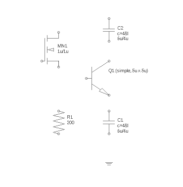 A new schematic usually starts with the components (=devices). To add a component in the schematic, choose the component from the components dock window and place it in the schematic. With a SHIFT and CTRL left mouse click you can rotate it before placing. A placed component will automatically get a device name and default parameters. To change this call Edit Item and double click on the component. A dialog with all parameters will appear.
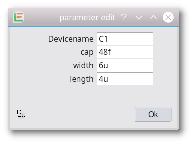
If the component has calculated or hidden parameters this dialog will have an option in the lower left to display the hidden parameter or calculation formula. As soon as a parameter is edited, a set callback will be called and calculated parameters are recalculated. Write protected parameters cannot be edited.
Placing two identical components over each other will convert the component to a component vector (called iterated instances with some other tools). These component vectors can be connected by a bus at each port, connected each instance of the component different. (Vector components were introduced with release 20180505)
Ports
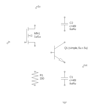 In a schematic is a port a single connection to the outside, which can be another schematic in a higher hierarchy level. The port name is always identical with the name of the wire connected to it. This is automatically ensured. In a symbol a port is the only allowed functional device. It defines the connections. Port names must be identical with the names of the connections in the layout. A bundle of connections can be archived with the Bus Port feature.
Wire
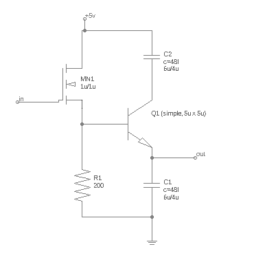 A wire represents a single connection between components, ports or buses. A wire will be named automatically. An explicit name can be given with the LabelNode feature. The color of all wires is the same and can be set in the SetupDialog. A wire should never be mixed up with a Line. Both shapes look similar, but a Line is not functional and will not connect anything. If a wire is connected with another wire it is marked with a dot. Two crossing wires without a dot are not connected. The concrete wire placemant is done in the WireMode.
Label Node
 By default, connections are named automatically as setup in the SetupDialog. With the Label Node feature a wire is given an explicit name. The name is displayed next to the wire. If the wire is already named, the existing name is placed. A label can be moved afterwards with the Edit Item feature.
Edit Schematic
In Edit Item use a right mouse click on any schematic element to edit it. A context menu with all edit options will be displayed. Available edit options depend on the choosen object. These options exist:
- show component info
- edit component parameter
- change component
- vector properies
- move label
- move
- copy
- rotate
- delete
- probe
- copy to clipboard
- paste from clipboard
- cancel editing
- set port name
- make port global
- remove global port attribute
- set color for non functional objects
- previous sheet
To edit more than one element simultaneously press and hold down the left mouse button to select the items.
© 2026 juspertor GmbH