Shape Utilities
Remove Small Edges
Small unwanted edges of selected elements are removed. If possible, vertical edges and horizontal edges remain unchanged. In a dialog, set the maximum length of edges you want to remove.
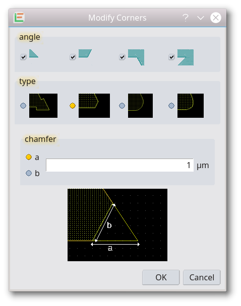
Modify Corners
This feature allows four different ways to modify the corners of selected shapes. All modifications can be limited to positive/negative angles or sharp angles. Paths and Boxes are converted to polygons by this operation. Zero width paths and partly selected paths are ignored.
| Supported Modifications | |
|---|---|
| Add/Remove Area | An area is added/substracted to each corner of selected shape. The size of the added area is proportional to the angle of the corner and negative for inside angles/corners. The first required value is the size of an equivalent square added for a right angle. The second value describes how the area is added. This feature may be used for a rule based optical proximity correction (OPC).  |
| Chamfer |  |
| Fillet Round |  |
| Fillet Bezier | 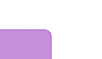 |
Usage:
- select shapes which should be modified
- to modify only some vertexes of a shape, select just the required vertexes with PointSelectMode
- call Modify Corners
Bow Improvement
In the electronic design area, bows are commonly handled as polygons with a certain resolution describing the bow. The required resolution can differ in different applications. While a reduction can be done with the Remove Small Edges feature, Bow Improvement can be used to increase the resolution. The bow is detected and replaced by a bow with more vertexes. (introduced with release 20220419)


Insert Slots
Film stress can be a technological problem for fabrication. To reduce stress in wide metal areas, small slots are inserted. This feature does slot insertion for all selected shapes. The required parameters can be set in a dialog. If the chosen parameter requires more than 20.000 slots, no modifications are made because the resulting polygons will no longer be handleable afterward. In this case, split the shapes before using the cut feature.
Separate Holes
The outer outline and the outline of holes can be moved to separate layers.
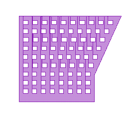
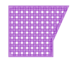
Convert to Mesh
In printed Circuit Boards (PCB) a good balance between metalized and blank areas is required. For an unused area, mesh will be used to achieve this. With Convert to Mesh, you can convert polygons and boxes to mesh. You will be prompted to enter width and spaces of the mesh.
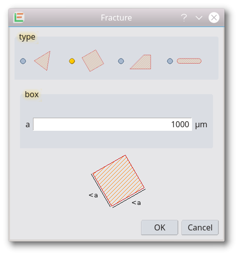
Facture
Selected shapes are split. There are four diferent types of resulting shapes:
| Supported Modes | |
|---|---|
| non overlapping triangles | 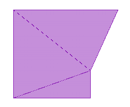 |
| overlapping rectangle, may be non-orthogonal orientation | 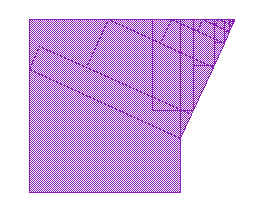 |
| non overlapping trapezoids | 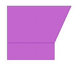 |
| overlapping lines | 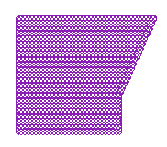 |
Strip Identical Element
Elements that are identical in shape and layer are impossible to see in the main display and often only recognized by the select counter. This feature will detect such double shapes and delete all copies except one in the current cell on all layers.
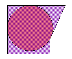
Add biggest inner Circle
The feature adds the biggest possible circle inside any selected shapes. As a result, the center of each circle is the pole of inaccessibility of a shape. All circles will be added to the active layer.
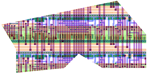
Crop
The complete cell will be cropped with selected shapes. Selected cell references will be ignored. All selected elements will be deleted after calling this feature. Required cell references will be flattened.
Usage:
- create shapes which should be used for cropping
- select these shapes
- call CropWithSelection
Punch
The complete cell will be punched with selected shapes. Selected cell references will be ignored. All selected elements will be deleted after calling this feature.
Usage
- create shapes which should be used to punch
- select these shapes
- call PunchWithSelection
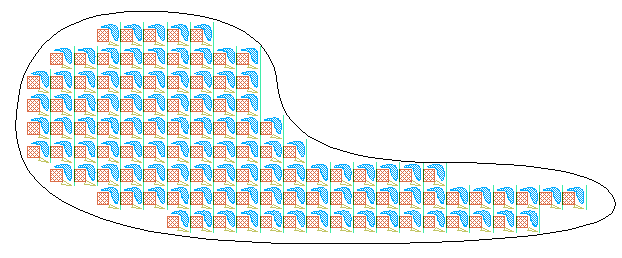
Fill Selected Shapes
Inside selected shapes references to an entered cell are inserted. The placement is done as an array and only placed if the binding box to the referred cell fits completely inside the selected shape. (introduced with release 20190409)
Usage:
- create shapes which should be filled
- select these shapes
- call Fill Selected Shapes
- a dialog will show up, choose the cell that should fill the selected shapes

© 2026 juspertor GmbH